Baja SAE ESP32 Systems
Project Statement:
The goal of this project is to design a system that can collect data from various sensors on the Baja SAE vehicle.
Below are schematics showcasing the design and layout of different ESP32 systems involved in the project.
Keep in mind: Components that have 5v inputs and outputs are connected to a logic level converter to convert the signals from 5v to 3v as the ESP32 can only handle 3v for the input signals.
Sensor Overview:
Schematics Overview:
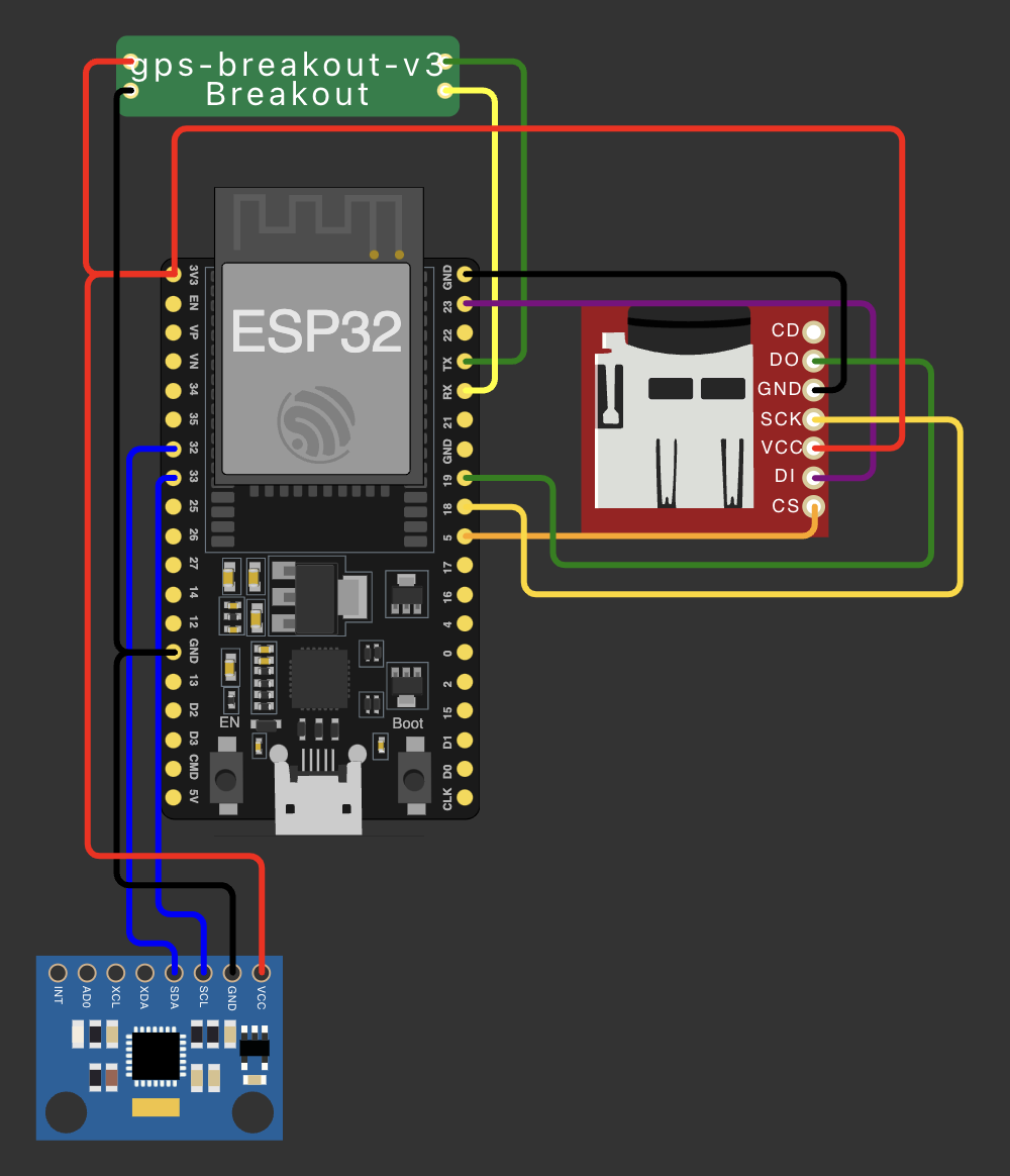
Dash Parent Schematic

Dash parent schematic representing the main ESP32 system used for the subsystem controls and recording, as well as the basic sensors.
- First, the dash ESP32 with will wait until it has a signal from a GPS satellite. This will give the system a time reference.
- Then, the "send" flag will be sent to the children ESP32s to start sending data. The signal will be send 1/3 of a second after another to make sure that each module is not sending data at the same time (this is done round-robin style, so if a signal is not detected it will not hinder the data recording).
- As the data is received, it is written to the SD card. The data is written in a CSV format with a time stamp, sensor ID, and sensor data.
- In between this data being sent, the GPS and Accelerometer data is also being recorded.
- This component is the most important as it is the central hub for all the data. If a child fails, this will be able to replicate some of the data.
- Components used: GPS (top-left, labeled: "gps"), Accelerometer (bottom-left), SD Card reader/writer (middle-right), and ESP32 (middle-left).
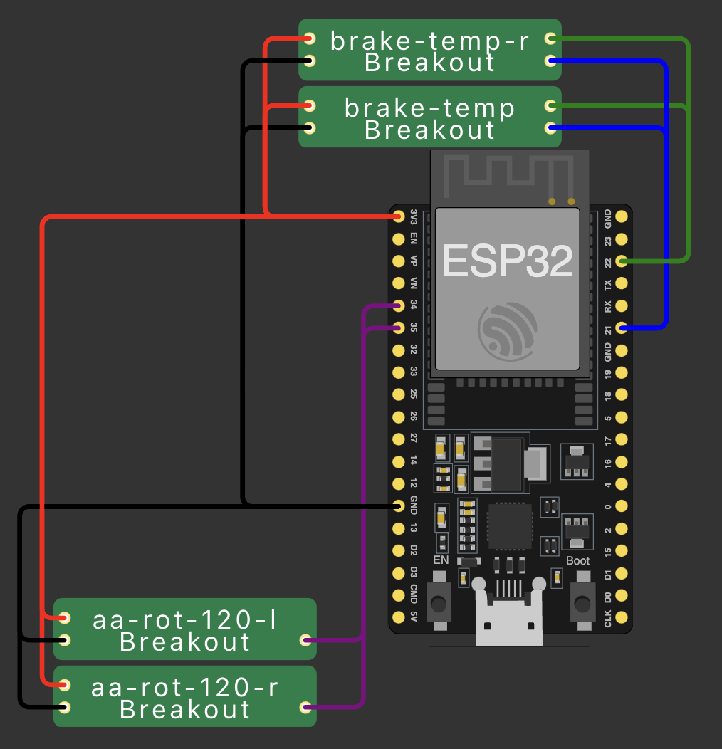
Front Child Schematic

Front child schematic representing the ESP32 module handling the front suspension sensors as well as the two front break temperature sensors.
- First, the front ESP32 will wait for a signal from the dash ESP32 to start sending and collecting data.
- The front ESP32 is responsible for collecting data from the front suspension height sensors and the front brake temperature sensors.
- The front ESP32 will then send this data to the dash ESP32.
- Components used: 2 suspension height sensors (bottom-left, labeled: "aa-rot-120" -r and -l), 2 brake temperature sensors (top-middle, labeled: "brake-temp" -r and -l), and ESP32 (middle). Not-Pictured: logic level converter.
Mid Child Schematic

This schematic details the mid-section ESP32 used for controlling and collecting data from many individual sensors.
- First, the mid ESP32 will wait for a signal from the dash ESP32 to start sending and collecting data.
- The mid ESP32 is responsible for collecting data from: 3 RTD temperature sensors, suspension height sensors for the rear left and right columns, and the rear brake temperature sensor.
- The mid ESP32 will then send this data to the dash ESP32.
- Components used: 3 RTD temperature sensors (far-right, labeled as "oil-Breakout"), 2 suspension height sensors (top-left, labeled: "sus-height" r and l), 1 brake temperature sensor (bottom-left, labeled: "brake-temp" r and l), and logic level converter (middle-right, labeled: "logic converter"), ESP32 (middle-left).
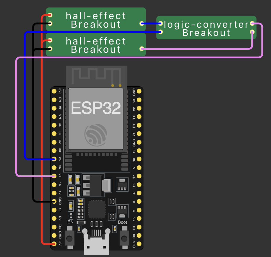
Rear Child Schematic

This schematic details the rear-section ESP32 used for controlling and collecting the RPM.
- First, the rear ESP32 will wait for a signal from the dash ESP32 to start sending and collecting data.
- The rear ESP32 is responsible for collecting data from the CVT input and output RPM sensors.
- The rear ESP32 will then send this data to the dash
- Components used: 2 Hall-Effect RPM sensors (top-left, labeled: "hall-effect"), logic level converter (top-right, labeled: "logic-converter") and ESP32 (middle).
ESP32 System Communication
All sensors communicate with each other using the ESPNOW protocol. This allows for low latency and high-speed communication between the ESP32 modules. As stated earlier: the Front, Mid, and Rear ESP32s each receive data from their respective sensors and send it to the Dash ESP32. The Dash ESP32 then sends the data to the SD card. After recording, a computer will be used for post-processing.
You can see an example of how this will be post-processed here.
Up Next...
Now that the ESP32 systems are designed and the sensors are chosen and wired correctly, the next step is to verify the system is working as intended. We will be doing this by having a Raspberry Pi computer receive the data from the Parent ESP32 via a LoRa module. This will allow us to see the data in real-time and verify that the data is being collected, sent and received correctly. This will also allow us to record the data in a different location for redundancy. Project updates will be posted as we progress.